Create your first mission
Start with a spacecraft
Build a minimal living mission on ASTROLAB Web: scenario, one spacecraft, updated 3D view, a first position plot, then save. The same workflow applies on Desktop (Platforms).
Goal: named scenario → spacecraft in the tree → 3D view updated → position plot in Dashboard → cloud save or .astrolab export.
Open Web App · need an account? Account and access
Stay inside Trial limits
The default scenario is already 12 h (Trial max) with a 120 s time step (Trial minimum). Start with a single spacecraft so the first session stays fast.
1 — Open Design
- Sign in at the Web app.
- You see Mission Tree (left), 3D scene (centre), Properties (right). At the top of the app, Design / Dashboard switches the centre view.
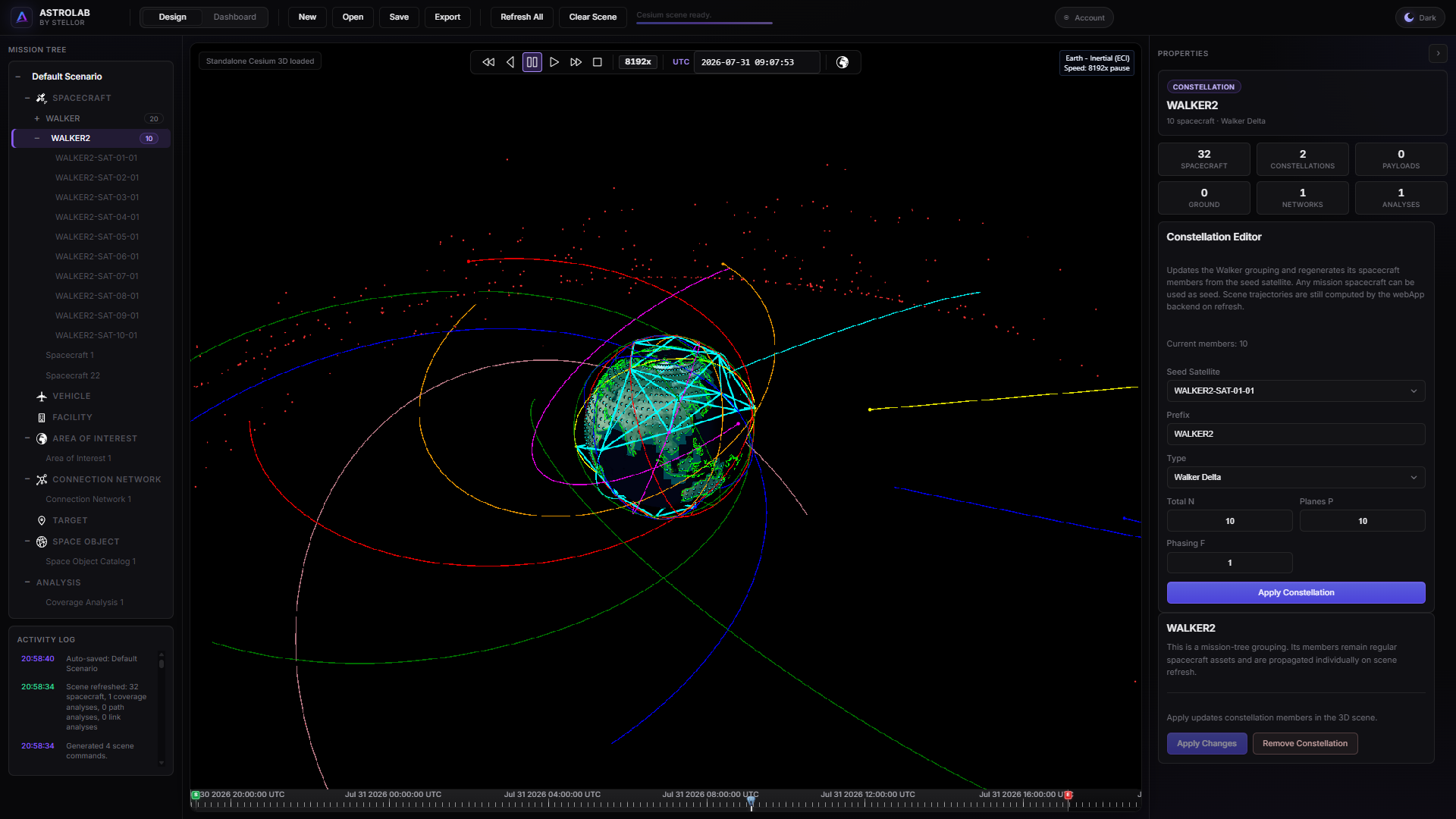
Design workspace — tree, scene, and properties.
2 — Scenario
- Select Scenario at the root of the Mission Tree.
- In Properties, give the mission a clear name (for example
Demo LEO). - Leave start and end as they are — a new mission already uses a 12 h window on the same calendar day (CET). That fits the Trial; you do not need to edit the dates for this walkthrough.
- Leave Scenario time step at 120 s. Trial cannot go below that.
3 — Add a spacecraft
The Mission Tree is driven by right-click on both Web and Desktop: add assets, remove them, and the other tree actions (children, constellation, run analysis, …).
- In the Mission Tree, right-click the Spacecraft category.
- Choose Add Spacecraft.
- Click the new spacecraft so Properties opens on the right.
To remove an asset later, right-click it in the tree and choose Remove.
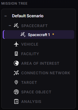
Adding a spacecraft from the Mission Tree.
4 — Create your orbit
- Give the spacecraft a clear name.
- Open the Orbit tab. Use the Orbit design wizard (or edit the state by hand — see Spacecraft).
- If you use the wizard: pick a class, set the parameters, then click Design orbit (document). The initial state fields below (SMA, inclination, RAAN, …) update in the mission document — check that they changed.
- Skip sensors, antennas and power for now — add them when you follow a tutorial.
Explore the Orbit wizard
Try a few preset classes — LEO Generic, SSO, GEO, and others. Each time, click Design orbit (document) and watch how the initial state changes. Then Apply Changes (next step) to push the orbit to the 3D scene. You do not need the “right” orbit for this walkthrough; the goal is to get comfortable with the wizard.
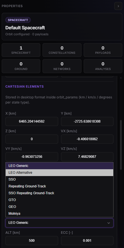
Spacecraft properties — name and orbit.
5 — Apply and view in 3D
- Scroll to the bottom of the spacecraft Properties panel and click Apply Changes. That pushes the orbit to Cesium — you do not need a separate Refresh scene for this step.
- Check that the spacecraft appears as a coloured marker on the trajectory and that the time bar matches your scenario window.
- Right-click the marker in the 3D view to follow the spacecraft in Cesium. The camera locks onto the satellite and the 3D model becomes visible (untracked spacecraft show as markers only).
flowchart LR
  Wizard["Orbit wizard"] --> Design["Design orbit (document)"]
  Design --> State["Check initial state"]
  State --> Apply["Apply Changes"]
  Apply --> View["Inspect in 3D"]
  View --> Follow["Right-click → follow"]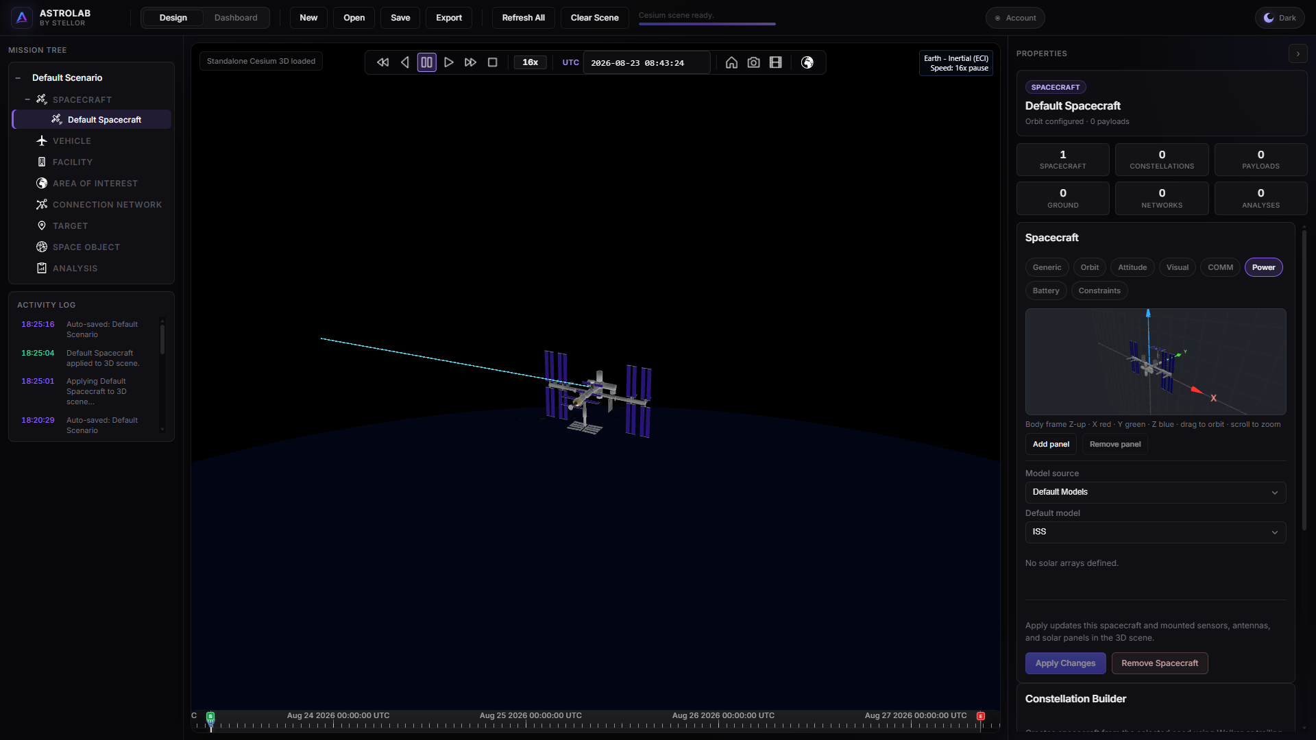
After Apply — spacecraft marker on the live trajectory; right-click to follow and see the model.
6 — 3D scene controls
The overlay at the bottom of the globe is the playback and camera bar. Use it to animate the scenario, jump in time, capture the view, and switch between 3D and 2D.

Playback, UTC time, camera tools, and 2D/3D toggle.
| Control | What it does |
|---|---|
| ≪ / ≫ | Slow down / speed up playback (1x, 2x, 4x, … — the badge shows the current multiplier) |
| ◀ | Play in reverse |
| Pause | Stop animation at the current time |
| ▶ | Play forward |
| ■ | Stop and jump back to scenario start |
| UTC field | Current scenario time (YYYY-MM-DD HH:mm:ss). Edit it and press Enter to jump |
| Home | Reset the camera to the default globe view |
| Camera | Download a PNG screenshot of the current view |
| Film / movie | Start or stop a WebM recording of the scene |
| Globe (rightmost) | Switch between 3D and 2D map. Click it to go to 2D; click again to return to 3D |
Both views show the day/night terminator (Earth’s shadow). Play the scenario and watch the shadow move with UTC time.
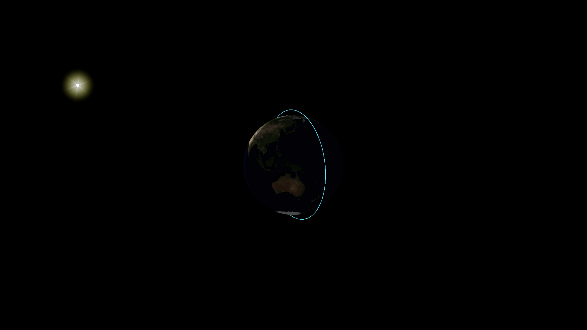
3D globe — lighting and terminator (shadow) on the Earth.
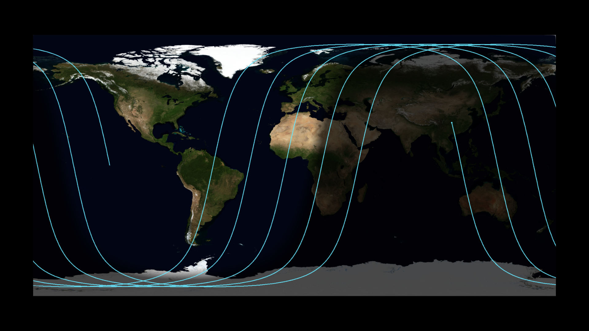
2D map — the same day/night shadow, after toggling the globe button.
Orbit the globe with left-drag and zoom with the wheel. Right-click a spacecraft marker to follow it, as in the previous step.
7 — Plot the position (Dashboard)
The 3D view shows the trajectory; Dashboard is where you generate plots and tabular reports from that spacecraft.
- At the top of the app, switch from Design to Dashboard.
- In Asset, select the spacecraft you just created.
- Browse the list of Plots (switch to Reports for tables). Spacecraft templates include position products such as S/C Position, Local Altitude (WGS84), and Geodetic Coordinates (Lat/Lon).
- Pick a position plot and click Generate Plot.
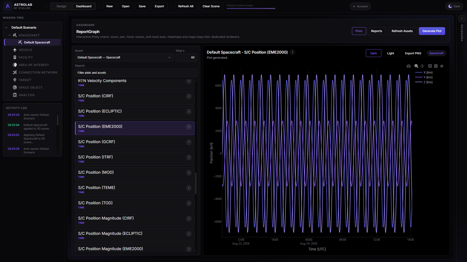
Dashboard — select the asset, pick a plot or report, generate.
8 — Save
- Cloud: Save mission so it counts against your plan quota.
- File: Export a
.astrolabfrom the top bar for backup or Desktop.
Checkpoint
You should have a named scenario, at least one spacecraft, the trajectory visible in 3D (and optionally followed from the marker), a position plot from Dashboard, and a saved mission (cloud and/or .astrolab).
Next steps
You are ready to run an analysis, not only visualise:
- LEO Optical Satellite — sun-synchronous imager, sensor, AOI, first analyses
- Or browse the Analyses catalogue
Deeper UI: Mission tree · Properties · Scene · Reporting