Antenna¶
Asset reference
Concept¶
An antenna is the RF aperture and radiation pattern on a spacecraft, facility, or vehicle. Link Complex transmitters and receivers read directional gain from a linked antenna on the same parent. Simple RF uses a fixed EIRP / G/T and does not need this asset.
Boresight is +Z. Mounting and pointing are the same model as sensors — Mounted assets. Changing the pattern does not by itself re-run Link; apply the antenna, then re-run the analysis.
When to use¶
| Use an antenna when… | You can omit it when… |
|---|---|
| Complex TX/RX budgets need gain vs off-boresight angle | Simple RF (implicit isotropic EIRP / G/T) |
| You want the 3D pattern lobe in Design | Geometry-only Link (no budget) |
Generic¶
| Parameter | Type | Default / options |
|---|---|---|
| Name | text | — |
| Active | checkbox | — |
| Parent asset | select | spacecraft, facility, vehicle |
| Role | select | tx / rx / txrx (default txrx) |
| Color | color | #FF8C00 |
| Mesh phi | integer ≥ 8 | 144 |
| Mesh theta | integer ≥ 8 | 72 |
Role is which chain may link this aperture (transmit, receive, or both). Mesh phi / theta is only the 3D lobe tessellation — denser mesh looks smoother and costs more to draw; it does not change the analytic gain used in Link.
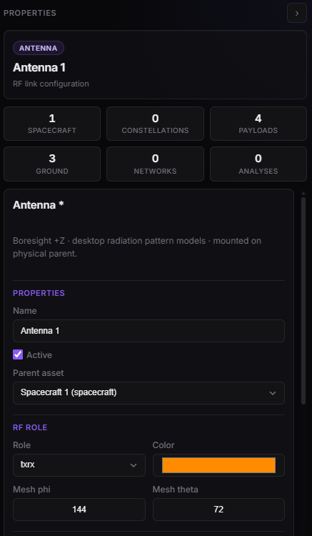
Antenna Properties — parent, role, color, mesh density.
Radiation patterns¶
Pattern model picks a catalogue entry. The fields below the dropdown then change. Switching model resets those parameters to that model’s defaults.
Define Using (aperture models)¶
Gaussian, Cosine Aperture, and Parabolic share a Define Using control:
| Mode | You set | The editor derives |
|---|---|---|
| beamwidth | 3 dB beamwidth | Diameter and peak gain |
| diameter | Physical diameter | Beamwidth and peak gain |
| gain | Peak gain [dBi] | Diameter and beamwidth |
Parabolic defaults to diameter. Frequency and aperture efficiency still apply in every mode. Backlobe gain floors the pattern behind the aperture.
Ideal and elementary¶
| Pattern (editor) | Use when… | Extra knobs |
|---|---|---|
| Isotropic | Constant gain in every direction (default; closest to Simple RF) | Frequency, aperture efficiency, Gain [dBi] (default 0) |
| Dipole | Short / half-wave element, not a dish | Length / wavelength (default 0.5), backlobe, Gain default 2.15 dBi |
Aperture and shaped beams¶
| Pattern (editor) | Use when… | Extra knobs |
|---|---|---|
| Gaussian | Smooth pencil beam, no explicit side-lobe structure | Define Using + backlobe |
| Cosine Aperture | Circular aperture with a cosⁿ taper | Define Using; optional exponent n |
| Parabolic | Reflector / dish sized by diameter or HPBW | Define Using; main-lobe half-angle |
| Rectangular Gaussian | Elliptical beam (different az / el widths) | Azimuth and elevation 3 dB beamwidths |
| Horn Rectangular | Pyramid / sectoral horn | HPBW in E-plane and H-plane |
| Patch Simple (microstrip) | Low-gain patch (typical ~6 dBi, 2.4 GHz default) | E- / H-plane HPBW |
| Array Factor (phased grid) | Regular planar array, including steered beams | Elements in X/Y, spacing in λ, steer θ / φ |
| Side-Lobe Template | Hand-placed first (and optional second) side lobes | Main HPBW, lobe levels / offsets / width |
| cosⁿ aperture | Smooth cosⁿ(θ) main lobe. Engineering model, not an ITU recommendation |
HPBW, optional exponent n |
| Parabola + side-lobe rings | Parabola or Gaussian main lobe plus three configurable rings. Not an ITU recommendation | Diameter, ring levels and offsets |
ITU-R reference patterns¶
These rows follow a published ITU-R recommendation. The link gain is the co-polar (or the single published) mask. Plots stay the generic antenna cuts; they are not a copy of a figure in the PDF. Numeric agreement is checked in tests/assets/test_itu_pattern_sources.py and tests/assets/test_bo1213_pattern.py.
A row is marked matches the PDF only where the equations below were read from that file. Anything the recommendation leaves open, or that this catalogue does not implement, is written in the same cell.
| Pattern (editor) | What the catalogue implements | |
|---|---|---|
| ITU-R BO.1213-1 (DTH receive) | BO.1213-1 (2005) | Matches Annex 1 co-polar, for D/λ ≥ 11. Peak gain is 10 log(η (π D/λ)²) from diameter, frequency and efficiency, not the Main Lobe Gain field. Figure 1 is the 60 cm / 11.7 GHz / η = 0.65 case. Cross-polar is computed for the tests; Link uses co-polar. |
| ITU-R S.465 (FSS coordination envelope) | S.465-6 (2010) | Matches §2: 32 − 25 log φ from φmin to 48°, then −10 dBi. φmin is max(1°, 100 λ/D) when D/λ ≥ 50, otherwise max(2°, 114 (D/λ)^(−1.09)). Inside φmin the recommendation does not define a main lobe; the catalogue holds Gmax unless Appendix 8 main lobe is on. Notes 4 and 5 (pre-1993 antennas, and φmin = 2.5° for some receive antennas) are not implemented. |
| ITU-R S.580 (GSO side-lobe objective) | S.580-6 (2004) | Matches recommends 1 and Note 5 for D/λ ≥ 50: 29 − 25 log φ from max(1°, 100 λ/D) to 20°, then −3.5 dBi until 26.3°, then S.465 (32 − 25 log φ until 48°, then −10 dBi). The recommendation applies within 3° of the GSO; the catalogue is axisymmetric, so that angular limit is not modelled. The main lobe inside φmin is unspecified; Appendix 8 is optional and off by default. |
| ITU-R S.731-1 (cross-polar) | S.731-1 (2005) | Matches recommends 2, which is a cross-polar reference, not a co-polar dish: 23 − 20 log φ from φr to 7°, 20.2 − 16.7 log φ to 26.3°, 32 − 25 log φ to 48°, then −10 dBi. φr = max(1°, 100 λ/D). Inside φr the gain is held at G(φr). Annex 1 (separate envelopes for D/λ ≥ 100 and D/λ < 100) is not implemented. |
| ITU-R S.672-4 (GSO satellite, single feed) | S.672-4 (1997) | Matches recommends 1 for a circular beam (z = 1, α = 2, a = 2.58, b = 6.32). ψb is half the 3 dB beamwidth. LN is the near-in side-lobe parameter (default −25 dB). For z = 1 the −20 dB and −25 dB rows of Table 1 give the same a. The recommendation does not define a and α for LN = −30 dB; the catalogue still uses a = 2.58 and α = 2. Elliptical beams (z ≠ 1) and the multiple-feed shaped beam in recommends 2 are not implemented. |
| ITU-R S.1528-1 (non-GSO satellite) | S.1528-1 (2026) | Matches recommends 1.2 for a circular beam (z = 1, α = 1.5, a = 2.58, b = 6.32, same LN parameter). This is a non-GSO satellite antenna, not an earth station. The D/λ < 35 MEO/LEO patterns are not implemented. |
| ITU-R BO.1445 (BSS sat fast roll-off) | BO.1445-0 (2000) | Matches Annex 1 co-polar Curve A for Regions 1 and 3: min(ΔG1, ΔG2), with Bmin = 0.6° and φ0 the full half-power beamwidth. Relative gain stops at −Gmax (0 dBi). Cross-polar Curve B is not the link gain. The beam is circular; the elliptical a, b form of Gmax is not applied — peak gain is the Main Lobe Gain field. |
| ITU-R F.699-8 (fixed service) | F.699-8 (2018) | Matches recommends 2. Main lobe Gmax − 2.5×10⁻³ (D φ/λ)² out to φm = 20 (λ/D) √(Gmax − G1), with G1 = 2 + 15 log(D/λ). For D/λ > 100 the plateau runs to φr = 15.85 (D/λ)^(−0.6), then 32 − 25 log φ. For D/λ ≤ 100 the plateau runs to 100 λ/D, then 52 − 10 log(D/λ) − 25 log φ. From 1 GHz to 70 GHz the skirt ends at 48° (−10 dBi if D/λ > 100, otherwise 10 − 10 log(D/λ)). From 70 GHz to 86 GHz it ends at 120° (−20 dBi, or −10 log(D/λ) when D/λ ≤ 100). Below 1 GHz, recommends 2.3 applies for D/λ > 0.63: the skirt ends at φs = 144.5 (D/λ)^(−0.2) and the floor is −2 − 5 log(D/λ). Gmax is the Main Lobe Gain field; recommends 3 estimates it as 20 log(D/λ) + 7.7 when only one of the two is known. The cross-polar sum in recommends 7 is an interference calculation between two antennas, not this pattern. |
Back-lobe gain is only a floor under the mask. The defaults sit below the published rear level (−10 dBi or 0 dBi), so they do not change these equations. Plots stay the generic antenna cuts.
Imported grid¶
Imported Grid (CSV/NPZ) uses a measured or external gain table instead of a catalogue formula. Link and the 3D lobe read that table. The design frequency on the antenna does not scale it.
On the web editor:
- Open the antenna and set Pattern model to Imported Grid (CSV/NPZ).
- Click Load from this computer and choose a
.npzor.csv(8 MB maximum). The file is stored in the mission. Pattern file then shows its name. - Or type a library file name, such as
stk_like_parabolic.npz, and leave it without an upload. - Set Gain unit to
dbwhen the file stores dBi, orlinearwhen it stores a power ratio. - Apply the antenna, then re-run Link. Changing the file does not refresh an old Link result.
An uploaded file travels with the mission, so the cloud analysis can read it. A typed name with no upload is looked up on the analysis machine: first as a path, then as a file in ASTROLAB’s radiation-pattern library. Editing the name after an upload drops the stored bytes and uses that lookup instead. The names in the table below are already in the library.
The desktop antenna dialog does not list this model. If you open an antenna that already uses it, the dialog shows Isotropic. Applying that dialog replaces the imported grid.
If the file is missing, empty, or the wrong shape, the pattern gain is 0 (no contribution to the link).
NPZ¶
A NumPy .npz with three arrays. gain_db has one row per theta sample and one column per phi sample.
| Key | Shape | Meaning |
|---|---|---|
theta_deg |
(N,) | Off-boresight angle, degrees, strictly increasing. 0° is boresight (+Z), 180° is the rear. N ≥ 2. |
phi_deg |
(M,) | Azimuth around boresight, degrees, strictly increasing. M ≥ 2. Use −180°…180°. Queries are folded into that range, so a 0°…360° axis clamps the negative azimuths to the first sample. |
gain_db |
(N, M) | Absolute gain in dBi, not dB below the peak. 0 is 0 dBi. |
theta_rad / phi_rad are accepted when the degree keys are absent; they are converted to degrees on load. If the file contains gain_linear, that array is the power ratio (1 = 0 dBi) and the Gain unit field is ignored. Negative linear samples are clipped to 0.
import numpy as np

theta_deg = np.linspace(0.0, 180.0, 91)
phi_deg = np.linspace(-180.0, 180.0, 73)
gain_db = np.zeros((theta_deg.size, phi_deg.size))
# gain_db[i, j] = G(theta_deg[i], phi_deg[j]) in dBi
np.savez("my_antenna.npz", theta_deg=theta_deg, phi_deg=phi_deg, gain_db=gain_db)
CSV¶
Same grid as text. The first cell of the header is ignored. The rest of that row is phi in degrees. Each following row starts with theta in degrees, then the gain cells. Lines whose first cell starts with # are skipped. With Gain unit db, the cells are dBi.
,-180,-90,0,90,180
0,30,30,35,30,30
90,0,2,10,2,0
180,-10,-10,-10,-10,-10
Angles between samples are interpolated. Outside the tabulated theta or phi, the gain stays at the nearest edge sample.
Library files¶
| File name | Contents |
|---|---|
stk_like_parabolic.npz |
Dish-like main lobe plus side lobes (default) |
parabolic_1m_10ghz.npz |
Parabolic sample, 1 m at 10 GHz |
dipole_half_wave.npz |
Half-wave dipole |
horn_rectangular_sample.npz |
Rectangular horn sample |
patch_microstrip_sample.npz |
Microstrip patch sample |
array_4x4_uniform.npz |
4×4 uniform array |
array_8x1_steered.npz |
8×1 array steered to θ = 25° |
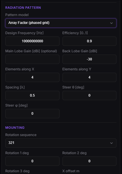
Antenna — Pattern model and the dynamic fields for the selected pattern.
Pointing¶
See Mounted assets (offsets, Euler sequence, Body-Fixed / Scanning / Conical Spin / Targeted). Off-boresight angle in Complex Link is this pointing plus the pattern above.
Plan limits¶
antennaPerParent at creation.