Spacecraft
Asset reference
Concept
In ASTROLAB a spacecraft is the central orbital actor of a mission study. It owns the dynamic state (orbit + attitude), participates in the 3D scene, and usually acts as the parent for payloads that see the Earth or talk to the ground: sensors, antennas, transmitters/receivers, solar arrays, and batteries.
Think of it as the digital twin of a satellite bus: mass and area properties feed drag/SRP and power; the propagator turns an initial state into an ephemeris over the scenario; attitude laws orient instruments and panels; constraints can further restrict when the spacecraft is allowed to “count” in access-like calculations.
Constellations do not replace spacecraft — a Walker or trailing constellation creates and groups member spacecraft that remain individually propagated.
Where in the UI
| Action | How |
|---|---|
| Create | Mission Tree → Spacecraft category → Add Spacecraft (desktop context menu or mobile ⋯) |
| Edit | Select spacecraft → Properties (tabbed editor) |
| Apply | Apply Changes when the header shows dirty * |
| Children | Add from tree under the spacecraft, or manage Power/Battery panels inside the spacecraft tabs |
Editor tabs
| Tab | Purpose |
|---|---|
| Generic | Identity, mass properties, propagator |
| Orbit | State / frame / orbit design wizard / external ephemeris |
| Attitude | Attitude law and parameters |
| Visual | 3D model, color, trail |
| COMM | Bus data-plane for Latency (MMFU, rates, processing) |
| Power | Bus size + solar array panels |
| Battery | Battery packs |
| Constraints | Access / environment constraints |
Generic
| Parameter | Type | Default | Notes |
|---|---|---|---|
| Asset ID | text | — | Display / report name |
| Active in scene refresh | checkbox | — | When off, skipped on scene refresh |
| Mass [kg] | decimal | 500 |
UI: Mass kg |
| Drag coefficient Cd | decimal | 2.2 |
|
| Geometric properties source | select | Constant Values / From Custom Assembly | Assembly needs a custom 3D design on the Visual tab |
| Area mode | select | Nominal / Randomly Tumbling / Max / Min | Only when From Custom Assembly |
| Drag area [m²] | decimal | 1 |
Locked when areas come from the assembly |
| SRP coefficient Cr | decimal | 1 |
|
| Reflectivity area [m²] | decimal | 1 |
Locked when areas come from the assembly |
| Propagator Type | select | Keplerian |
See table below |
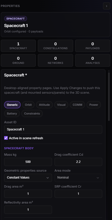
Spacecraft Properties — Generic (mass, Cd, areas).
Propagator types
Apply Changes refreshes Design with the selected propagator (Keplerian, Eckstein–Hechler, DSST, or Numerical). Analyses that propagate the bus use the same choice.
| Propagator | Description |
|---|---|
| Keplerian | Two-body analytical |
| Eckstein Hechler | Analytical (LEO-style perturbations) |
| DSST Propagator | Semi-analytical — efficient on long horizons |
| Numerical Propagator | Numerical integrator + force models (table below) |
Numerical propagator options
Visible only when Propagator Type = Numerical Propagator:
| Parameter | Type | Default |
|---|---|---|
| Min step [s] | decimal | 0.001 |
| Max step [s] | decimal | 300 |
| Abs tolerance | decimal | 1e-6 |
| Rel tolerance | decimal | 1e-8 |
| Gravity field Degree | integer | 4 |
| Gravity field Order | integer | 4 |
| Include atmospheric drag | checkbox | off |
| Atmosphere model | select | NRLMSISE-00 (also DTM2000, Harris-Priester, Simple Exponential, JB2008) |
| Space weather source | select | CSSI Space Weather / Marshall Solar Activity Forecast |
| Solar activity | select | Low / Moderate / High |
| Include solar radiation pressure | checkbox | off |
| Include third-body point masses | checkbox | off |
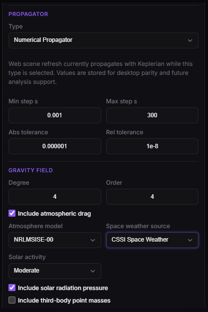
Spacecraft Properties — Generic (identity and propagator).
Orbit
| Parameter | Type | Options / notes |
|---|---|---|
| Epoch start UTC | text | Locked if external ephemeris is on |
| Epoch end UTC | text | Locked if external ephemeris is on |
| Coordinate frame | select | Inertial: EME2000, GCRF, TEME, TOD, MOD, CIRF, ECLIPTIC · Earth-fixed: ITRF |
| State type | select | Cartesian, Keplerian, Equinoctial, Delaunay — Keplerian/Equinoctial/Delaunay require an inertial frame (not ITRF) |
State elements by type
| State type | Parameters |
|---|---|
| Keplerian | SMA [km], ECC [-], INC [deg], RAAN [deg], AOP [deg], TA [deg] |
| Cartesian | X/Y/Z [km], VX/VY/VZ [km/s] |
| Equinoctial | a [km], ex, ey, hx, hy, Lv [deg] |
| Delaunay | L/G/H (×1e6), l/g/h [deg] |
Orbit design wizard
Writes a designed orbit into the document when you click Design orbit (document) (Apply still required for the scene). Check that the initial state fields updated before applying.
| Wizard class | Key parameters (min–max, default) |
|---|---|
| LEO Generic | alt_km 200–2000 (500), ecc 0–0.1 (0.001), inc_deg 0–180 (98.6), aop/raan/ta 0–360 |
| LEO Alternative | perigee/apogee alt 200–2000, inc, aop/raan/ta |
| SSO | alt 400–900 (700), ecc, mltan_h 0–24 (10.5), aop/raan/ta |
| Repeating Ground-Track | revolutions 1–200 (14), cycle_days 1–100 (1), ecc, inc, raan, aop |
| SSO Repeating (I/D) | i 1–15 (3), d 2–20 (10), ecc, aop/raan/ta |
| GTO | perigee 200–2000 (250), apogee fixed ~35786 km, inc 0–90 (27) |
| GEO | alt fixed ~35786 km, ecc 0–0.01, inc 0–10 |
| Molniya | perigee 500–1000 (600), apogee 39000–41000 (40000), inc ~63.4°, aop often 270° |
External ephemeris
| Parameter | Type | Notes |
|---|---|---|
| Use external ephemeris file | checkbox | Locks manual orbit editing |
| Load ephemeris file | file | .txt, .eph, .oem |
| Ephemeris file / external epoch | readonly | Filled after load |
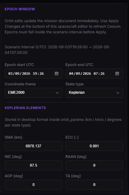
Orbit — frame and state vector.
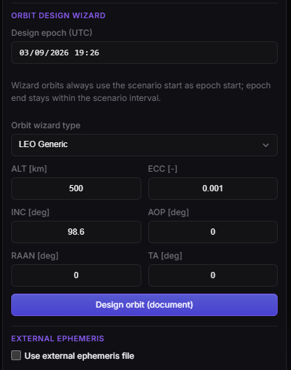
Orbit — design wizard (SSO, LEO, GEO, …).
Attitude
| Parameter | Type | Options |
|---|---|---|
| Attitude law | select | Nadir, LVLH, QSW, TNW, VVLH, Inertial, Sun Pointing, Spin-Stabilized |
| Law | Extra parameters |
|---|---|
| Nadir | — |
| LVLH / QSW / TNW / VVLH | Roll/Pitch/Yaw [deg], Rotation order (XYZ…ZYX) |
| Inertial | Inertial frame (EME2000, GCRF, TEME, TOD, MOD, CIRF, ECLIPTIC) |
| Sun Pointing | Sun axis X/Y/Z (default Z = −1) |
| Spin-Stabilized | Base frame (Inertial/LOF), frame select, spin axis (±X/Y/Z), spin rate [deg/s] |
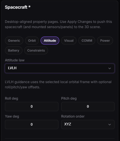
Spacecraft Properties — Attitude (nadir and other laws).
Visual
| Parameter | Type | Default |
|---|---|---|
| Model | select | From resource catalog, or Point only |
| Color | color | #66E8FF typical |
| Model scale | decimal | Normalized Cesium scale |
| Trail [s] | decimal | 3600 |
| Show orbit path | checkbox | on |
| Show label in scene | checkbox | off |
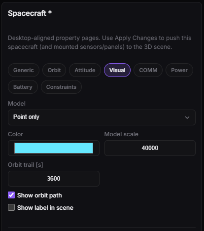
Spacecraft Properties — Visual (model, color, trail).
COMM (spacecraft bus)
This tab is the data-plane size of the bus for Latency: how fast data is produced, how much can sit onboard, and how fast it can leave on a downlink or ISL. It is not the RF budget — EIRP, G/T, and margins live on Transmitter / Receiver and Link.
Each field is a value + unit pair.
How Latency uses the bus
Coverage answers when you acquire. Latency then moves bytes along a Connection Network. The spacecraft COMM fields are the caps on that move.
flowchart LR
  Cov["Coverage window"] --> Acq["Acquisition data rate"]
  Acq --> Mmfu["MMFU onboard"]
  Mmfu --> Isl["ISL data rate"]
  Mmfu --> Dl["Downlink data rate"]
  Isl --> Mmfu
Dl --> Gnd["Facility"]| Field (editor) | Default | Where Latency uses it |
|---|---|---|
| MMFU capacity | 512 GB | Onboard mass memory. Acquired bytes accumulate here until a contact can drain them. If the tank fills, later data overflows (not delivered). |
| MMFU initial fill | 0 GB | How full the memory is at the start of the study. Non-zero fill means you already have a backlog before the first acquisition. |
| Acquisition data rate | 150 Mbps | How fast this bus produces data while Coverage says it is acquiring — only if the acquirer is the spacecraft (no sensor, or Coverage picked the bus). Bytes ≈ rate × time. If Coverage’s acquirer is a sensor, Latency uses that sensor’s Acquisition data rate (default 80 Mbps) instead; the bytes still land in this spacecraft’s MMFU. Discrete Acquirer rate × acquisition window uses the same rule. Discrete Fixed payload size ignores this rate and uses the size you set on Latency. |
| Downlink data rate | 450 Mbps | Space → ground hop. The hop is limited by the slower of this rate and the facility’s Downlink max RX rate. Used whenever the route includes a downlink (direct or last hop after ISL). |
| ISL data rate | 200 Mbps | Spacecraft → spacecraft hop when Latency policy is Use CN nodes as relay. That relay policy is the next Beta (Pro+). Unused while policy is No inter-satellite link. |
| Processing latency | 5 s | Fixed onboard delay on the relay / processing path (not the Coverage acquisition clock). Added when the bus handles the message — store-and-forward and ISL relays feel this. |
| Uplink data rate | 2 Mbps | How fast the bus can receive from the ground (user / session / TT&C-style inbound). Matters for Static Continuous session (and similar inbound) stories; it is not the downlink dump rate. |
| Max. concurrent link | 1 | How many ground/user sessions this bus may hold at once. Latency drops extra assignments when the cap is exceeded (typical IoT / session crowding). |
Sensor vs bus: production rate comes from the Coverage acquirer. Memory and space-to-ground / ISL drain always come from the parent spacecraft COMM tab.
Facility COMM (on the station asset) is the other half of a downlink: ingest rate, ground buffer, ground processing delay — Facility.
After you change these numbers, re-run Latency (it goes stale). Changing COMM does not by itself recompute Coverage or Link.
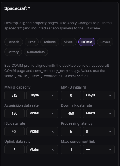
Spacecraft Properties — COMM (MMFU, rates, processing, concurrent links).
Power (solar arrays)
Solar arrays are child assets (solar_array) edited inside this tab (no standalone web editor).
| Control | Meaning |
|---|---|
| Add panel / Remove panel | Create/remove solar_array children |
| Model source | Custom Design (bus X/Y/Z [m]) or Default Models |
| Per panel | Asset ID, Mount face (±X/Y/Z), Pos X/Y/Z [m], Euler sequence, R1/R2/R3 [°], Dim X/Y/Z [m], Use SADM, Pointing (Fixed / Sun-Tracking), SADM axis, Area [m²] (default 5), Efficiency (default 0.3) |
Plan limit
solarArrayPerParent caps how many panels you can add per spacecraft.
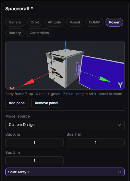
Power — bus size and model source.
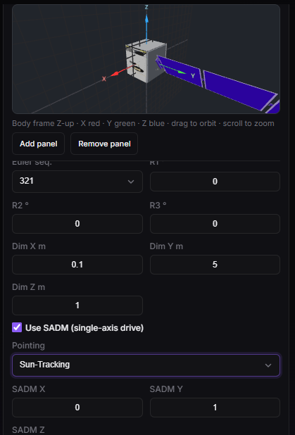
Power — solar-array panel card.
Battery
Batteries are child assets (battery) edited in this tab.
| Group | Parameters |
|---|---|
| Generic | Battery ID; Battery Type preset (Generic Li-Ion / LiFePO4 / NiH2) — applies chemistry defaults |
| Energy | Nominal Capacity [Wh] (default 500), Initial / Min / Max SOC [%] |
| Charge/discharge | Charge/Discharge efficiency [%], Max charge/discharge power [W] |
| Electrical bus | Nominal / Min / Max voltage [V] |
| Advanced | Self-discharge [%/day], Capacity degradation [%/yr], Min/Max operating temp [°C] |
Validation: non-empty ID; capacity > 0; 0 ≤ min SOC ≤ max SOC ≤ 100; initial SOC in 0–100; nominal voltage > 0.
Plan limit
batteryPerParent caps batteries per spacecraft.
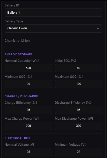
Spacecraft Properties — Battery (packs and SOC limits).
Constraints
| Constraint type | Default parameters |
|---|---|
| Range | min_km 0, max_km 2000 |
| Ground elevation | min_deg 10, max_deg 90 |
| Eclipse state | not_in / in |
| Target illuminated | (flag only) |
| Ground sun zenith angle | min_deg 0, max_deg 80 |
| Altitude | min_km 0, max_km 2000 |
| Solar beta angle | min_deg -90, max_deg 90 |
Each constraint card has Enabled and Remove.
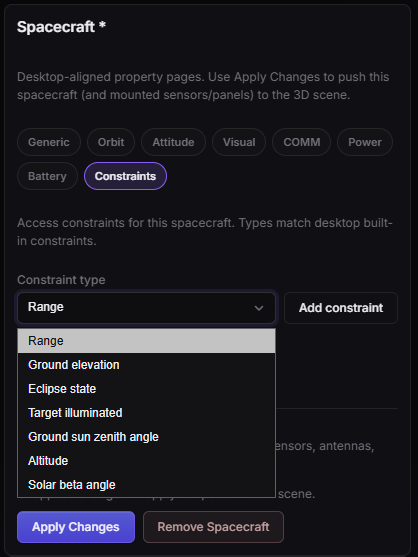
Spacecraft Properties — Constraints (type, Enabled, parameters).
Allowed children
| Child type | How |
|---|---|
| sensor, antenna, transmitter, receiver | Tree → Add under spacecraft |
| solar_array, battery | Power / Battery tabs (preferred on web) |
Example workflow
- Add Spacecraft, set Asset ID
SAT-DEMO. - Orbit wizard → SSO, altitude 700 km → Design orbit (document) → check that the initial state fields updated.
- Attitude → Nadir.
- Power → Add one sun-tracking panel.
- Battery → Add Generic Li-Ion, 500 Wh.
- Apply Changes (updates the 3D scene).
- Optionally attach a sensor, then create Coverage / Power analyses.